Microarray Pins ChipMaker Technology
Data Sheet
![]() Shop this product in our online store
Shop this product in our online store
Arrayit | ChipMaker microarray manufacturing contact printing spotting pins printheads CMP3 life sciences research
Tools - Microarray Printing - Microarray Pins ChipMaker™ Technology
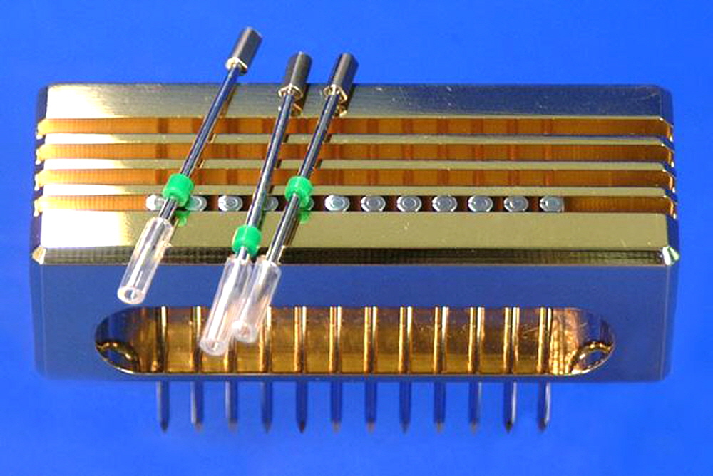
Arrayit's original Micro Spotting Technology for use with existing three-dimensional motion control systems for microarray manufacturing.
Description of ChipMaker™ Technology
ChipMaker™ Micro Spotting Pins and Printheads represent Arrayit’s original patented printing technology, protected by United States Patent 6,101,946. Still in wide use, ChipMaker™ technology is based on proprietary engineering and surface chemistry technologies, and the ChipMaker™ Micro Spotting Device has been specifically designed for a broad range of microarray manufacturing applications. The ChipMaker™ Micro Spotting Device is suitable for preparing solid surface microarrays of cDNAs, ESTs, oligonucleotides, peptides, proteins and other biological molecules used in fluorescence-based detection microarray assays.The ChipMaker™ Micro Spotting Device can be attached to virtually any high-end motion control system using the two threaded mounting holes on the back of the Printhead, and detection or printed microarrays is achieved using commercially available microarray instruments sold by PerkinElmer, Biorad, Axon, and others. Contact Arrayit for details on any of these products.
For best results, samples should be purified prior to printing. Arrayit’s PCR Purification Kits work well to purify double-stranded cDNA molecules. Other purification kits leave trace contaminants that may clog ChipMaker™ Pins and cause unwanted variation in signal intensity. Samples should be suspended in Arrayit Printing Buffer prior to manufacture. Arrayit’s Super and Mirror Microarray Substrates provide superior printing surfaces.
Arrayit assures the performance of all ChipMaker™ products. The finest scientific and engineering research went into the development of these products. Rigorous quality control monitoring of each part guarantees that the Pins and Printheads exceed the highest industry standards.
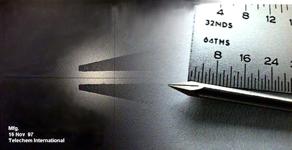
Fig. 1. ChipMaker™ Pin. Shown is a composite image of Arrayit’s ChipMaker™ Pin from 1997, including the flat, horizontally level tip and the exterior uptake channel that holds a predetermined volume of sample. These are two key aspects of Arrayit’s patented technology.
How to care for your ChipMaker Micro Spotting Device:
The ChipMaker™ Micro Spotting Device is designed and engineered for optimal wear and durability, while providing the highest printing performance in the picoliter and low nanoliter range. The Pins and Printhead have been tested out to 1 million printing cycles with no loss of printing precision or performance. Maximum durability requires proper use. Improper use of these precision products can lead to loss of performance or permanent damage. To avoid damaging your ChipMaker™ Micro Spotting Device, please follow these guidelines:
- The Printhead should be mounted on the motion control system prior to inserting the Pins into the Printhead. All hardware, motion control movements, calibration and software should be completely checked prior to inserting the Pins into the Printhead. Once the Pins are carefully inserted into the printhead, Pins can be damaged by inappropriate use. Pins must never be dropped, slammed or dragged across solid surfaces. Any contact of this type can permanently damage the tips of Micro Spotting Pins. Pay particular attention to the Z-axis speed settings and use the recommended settings in this protocol.
- If a loss of printing quality is observed, the spotting pins should be cleaned by carefully using the Pin and Printhead Cleaning Kit. Never subject ChipMaker™ parts to extremes in temperature or pH and avoid the use of strong solvents as these may damage the pin surface chemistry. Never dry Pins using canned air because the propellants ruin the surface tension properties needed for reliable printing.
- Microarray experiments depend upon the quality of the samples. Samples prepared by standard purification procedures can result in pin clogging and a loss of microarray quality. For best results with PCR products, use Arrayit’s PCR Purification Kits. Increased performance can also be obtained by using Arrayit’s Printing Buffers and Super Microarray Substrates.
- WARNING: Pressurized air canisters and other sources of pressurized air contain organic propellants that ruin the surface tension properties of pin tips. Do not use pressurized air canisters to dry your pins!! Use the Microarray Air Jet for this purpose.
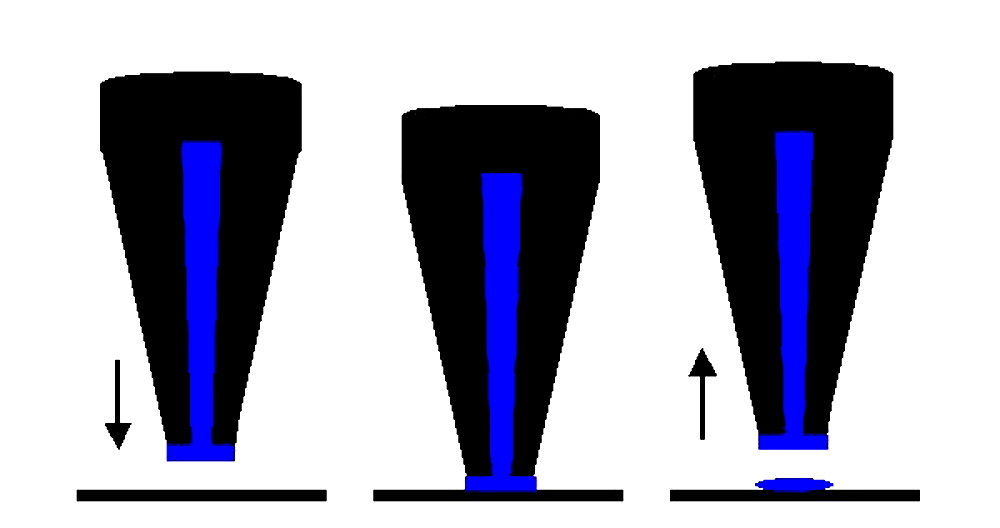
Fig. 2. Printing mechanism. Arrayit's unique printing technology (U.S. patent 6,101,946) enables high-speed manufacture of microarrays on glass, gels, membranes and other microarray surfaces. The pins have flat tips and defined uptake channels, which allows a thin (25 µm) layer of sample to form at the end of the pin, and printing to proceed by gentle surface contact. Printing occurs as a simple 3-step "ink-stamping" process as follows: (left) downstroke, (center) contact, and (right) upstroke. Pin tips and channels are available in a wide assortment of dimensions, allowing users to specify spot diameter and the number of spots per loading.
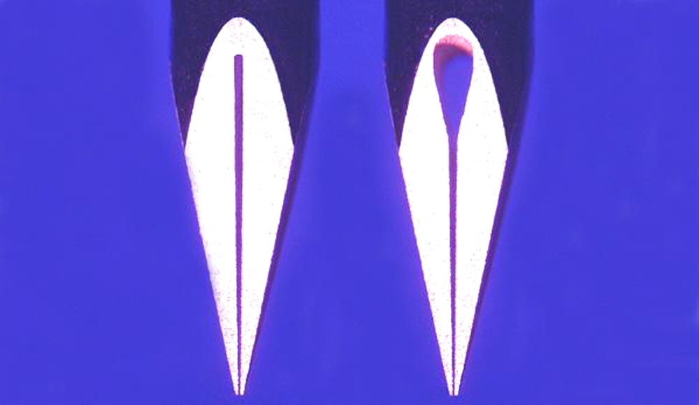
Fig. 3. Pin tip uptake channels. Shown are the standard 0.2 µl uptake channel (left) and the 0.6 µl “bubble” uptake channel (right). Both types of uptake channels fill completely with sample, and hold a predetermined volume.
Product Specifications
- Printheads hold 32 or 48 pins
- Feature size of 100-300 µm depending on pin tip
- Printing precision of ±15 µm
- Speed of up to 48 features/sec
- 4.5 mm pin offsets printing 18 x 36 mm microarrays with 32 pins
- Pin loading volumes of 0.20 µl (standard) and 0.6 µl (bubble)
- Delivery volumes of 0.7-5.2 nl depending on pin tip and uptake channel
- Print from either 96- or 384-well plates
- High-throughput of 50 microarrays of 10,000 features in <8 hrs
- 25,000 features in a 18 x 36 mm area
- Attach to any high quality motion control system
Motion control parameters*:
- Non-surface contact: X, Y, Z motions
- Surface contact: Z only!
- Sample loading time: 2-3 sec
- Pin wash time: 3 cycles at 1-3 sec/cycle
- Z axis surface clearance: 1.0-1.5 mm
- Z axis acceleration: 30 cm/sec2
- Z axis velocity: 10-20 mm/sec
- Z axis travel (surface = 0): +0.5-1.0 mm
- Surface dwell time: 0.05 sec
- Cycle time (32 pins): 32 features/sec
*All motion control parameters are suggestions only. Each of these parameters should be empirically tested with a single spotting pin to test printing quality and pin durability. Parameters can be modified to maximize printing quality and speed in a manner compatible with your motion control system. Changes in Z axis surface clearance, acceleration, velocity and travel should be made with extreme care!
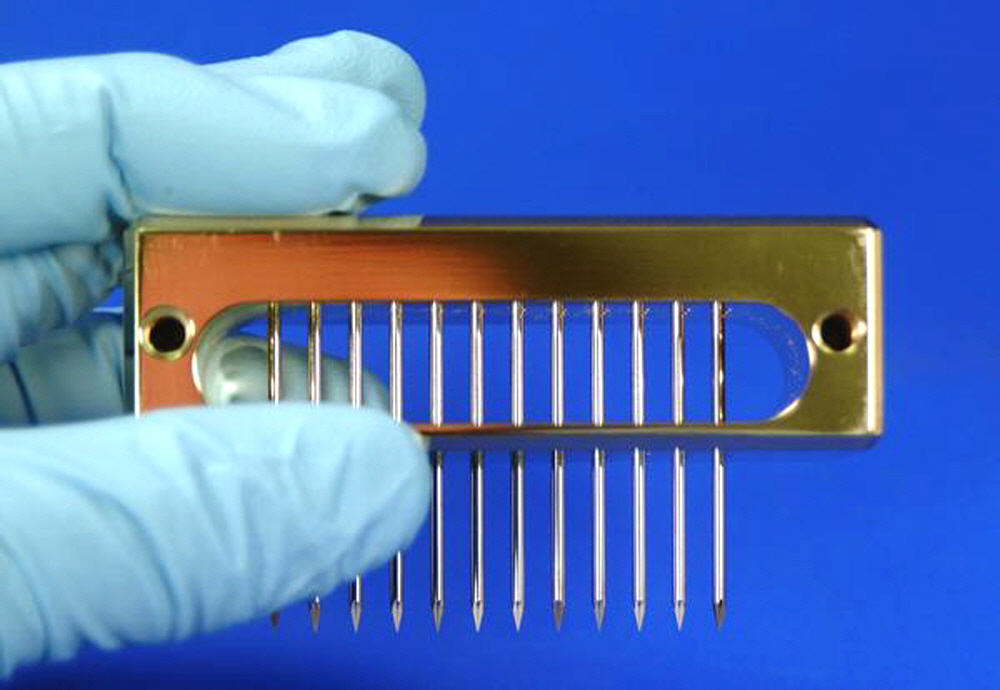
Fig. 4. ChipMaker™ mounting ports. Threaded mounting ports on the back side of each ChipMaker™ Printhead allow easy attachment to a motion control system.
Troubleshooting Tips
- Inconsistent printing
- Clogged pins-adjust wash/dry parameters
- Contaminated samples-use PCR Purification Kits
- Poor slide quality-use Super Microarray Substrates
- Poor printing buffer-use Arrayit Printing Solutions
Pin tip blunting
- Incorrect motion control parameters. Arrayit Pins do not require a tapping force for printing. Please do not tap our pins during the printing process.
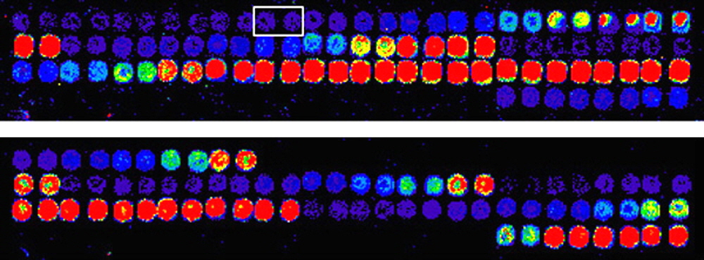
Fig. 5. ChipMaker™ microarray data. Fluorescent oligonucleotides were printed in duplicate onto glass substrates at 150 µm spacing using ChipMaker4 pins, scanned with a ScanArray 3000 (PerkinElmer) at 72% PMT and 60% laser in the Cy3 (top) and Cy5 (bottom) channels. Duplicate spots (rectangle) correspond to 0.6 fluors/µm2. Data are coded to a rainbow palette.
Technical Assistance
Please contact us if you have any comments, suggestions, or if you need technical assistance. By electronic mail: arrayit@arrayit.com (under the subject heading please type ArrayIt® technical assistance). By email: arrayit@arrayit.com, Monday–Friday PST 9:00am - 4:30pm. Please remember that we want to hear about your successes!
Notes on Microarrayer Wash/Dry Stations
Three keys to the proper function of wash/dry stations are:
- continuous source of filtered dH2O
- sufficient vacuum strenght to dry the pin tips
- proper motion control programming
Wash water should be continually replenished during a print run to avoid build up of used samples. Accumulating used sample can cause serious cross-contamination of printed arrays. A vacuum dry station relies on the passage of air across the pins tips to achieve drying. Multiple wash/dry cycles are necessary to ensure the complete cleaning of the pin tip and the removal of the previous sample. The most frequent cause of poor pin cleaning is excessive vacuum drying during the first wash/dry cycle. The first two or three cycles should employ short (0.5 sec) wash and dry steps, followed by a longer (5-10 sec) dry step once the previous sample has been washed away completely. The use of a long dry step during the first wash/dry cycle can cause the previous sample to dry inside the pin channel, leading to poor printing and cross-contamination of successive samples. Pins that are cleaned properly should produce less than 0.001% cross-contamination from one printing cycle to the next.
Warranty
ArrayIt® Brand products have been scientifically developed and sold for research purposes only. Extreme care and exact attention should be practiced in the use of the materials described herein. All ArrayIt® Brand products are subject to extensive quality control and are guaranteed to perform as described when used properly. Any problems with ArrayIt® Brand products should be reported to Arrayit immediately. Arrayit's liability is limited to the replacement of the product, or a full refund. Any misuse of this product is the full responsibility of the user, and Arrayit makes no warranty or guarantee under such circumstances. These materials are not to be administered to humans under any circumstances.

